
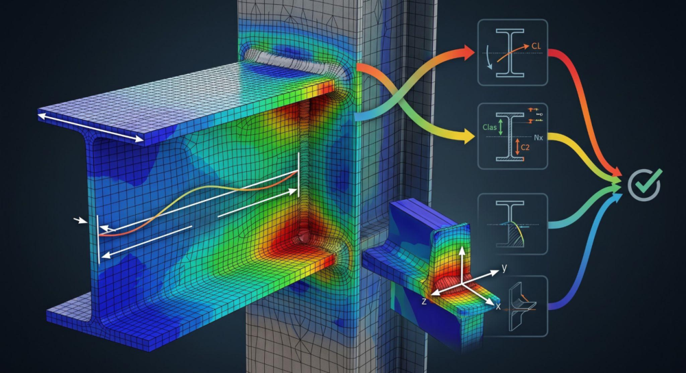

A solver returns stress fields, displacements, and element forces. EN 1993 and AISC 360 ask for something else: a cross-section class, a section modulus, stress components resolved in the plane of a weld throat, and the length between lateral restraints. Getting from one to the other takes a sequence of separate operations.
This article traces those operations for steel members and identifies which of them a program takes over. That split drives both the completeness of the verification and the time it takes to deliver the calculation package.
Where a steel section check starts?
A bending check to EN 1993-1-1 starts with the cross-section class. That parameter does not appear anywhere in a standard set of finite element results.
Classification compares the width-to-thickness ratio of every compressed part of the profile against limits scaled by ε = √(235/fy). For S355, ε = 0.814.
A web in bending holds Class 1 up to c/t = 58.6, and Class 3 runs out at 100.9. The same web in uniform compression holds Class 1 only to 26.8, with Class 3 ending at 34.2.
The class decides which section modulus enters the check: plastic, elastic, or the reduced effective value that EN 1993-1-5 derives from the effective width of the compressed parts.
Class 4 sections add an iteration. Effective width depends on the plate slenderness λ̄p = √(fy/σcr), and the critical stress in that expression follows the actual stress distribution across the compressed part.
Reducing the section shifts its centroid, the stress distribution shifts with it, and the calculation repeats until it converges. Run by hand, that loop only gets completed for sections picked in advance as governing.
The least favorable class of any single part governs the whole section. A web and a flange of the same profile land in different classes routinely, and the worse of the two carries into the check.
None of this comes out of the analysis itself. A standard result set holds neither the steel grade nor the breakdown of the profile into its individual compressed parts with their c/t ratios.
Section class moves with the load combination
The limits are tabulated separately for pure bending, pure compression, and the stress distributions in between. The load combination sets that distribution.
A rolled 457×152×82 I-section in S355 has a web at c/t = 38.8. In pure bending, that is Class 1 with room to spare. In uniform compression, the same profile drops to Class 4: the Class 3 limit here is 34.2, and the web does not meet it.
Between those two states sits the whole field of combined loading, where the class follows the position of the neutral axis, which is to say the ratio of axial force to moment in the particular combination.
For members subject to combined loading, the applicable classification can depend on the stress distribution produced by the load combination. Where that distribution changes materially between combinations, the classification needs to be reassessed.
A shell element does not output bending stress
Beam elements hand over internal forces directly: axial force, shear in two directions, and moments about both axes.
The failure mode here involves local axis orientation. A strong and weak axis swap, and a moment gets compared against the section modulus of the wrong plane.
Shell elements report top and bottom surface stresses plus moment resultants per unit width. Code checks need those values split into a membrane component (the half-sum of the surface stresses) and a bending component (the half-difference).
The twisting moment Mxy sits apart from both. A plate carries moment in two directions at once, and checking the larger of Mx and My while ignoring Mxy understates the actual stress state.
The next step recovers section forces by integrating membrane stresses along a cut line. This is where a general-purpose post-processor and structural FEA software part company, the latter running that reduction automatically.
Section forces come back together with the panel geometry, its thickness, and the edge restraint conditions, the inputs a plate buckling check needs.
A weld is checked in its own axes
A fillet weld under EN 1993-1-8 is verified by the directional method. The force on the throat resolves into three components: σ⊥ normal to the throat, τ⊥ shear transverse to it, and τ∥ shear along the weld axis. Two criteria apply at the same time:
√(σ⊥² + 3(τ⊥² + τ∥²)) ≤ fu/(βw·γM2) and σ⊥ ≤ 0.9·fu/γM2
The correlation factor βw depends on the steel grade: 0.8 for S235, higher for stronger grades. With γM2 = 1.25, the product βw·γM2 for S235 comes to exactly one, so the first criterion reduces to comparing the equivalent stress against the ultimate tensile strength.
The second caps the normal component at 0.72fu. Which of the two governs depends on how the force divides between the normal and the shear components.
The code also permits a simplified method: the resultant of all forces per unit length of weld goes against fu/(√3·βw·γM2), with no resolution into components. The standard states that for the same joint this route returns the more conservative answer.
The resolution happens in the weld’s own coordinate system. Analysis output arrives as a stress tensor in global or element axes, so every weld segment needs its own transformation. On a model carrying hundreds of meters of weld, that transformation is most of the connection check.
Some inputs live in the model topology
Some of the parameters a code check needs are set by how the elements connect to each other. They are absent from the results file.
Chapter F of AISC 360 builds flexural strength around Lb, the unbraced length between lateral restraints. While Lb stays within Lp, the full plastic moment governs. Between Lp and Lr the member goes into inelastic lateral-torsional buckling, with strength interpolated linearly across that range.
Beyond Lr, the calculation switches to an elastic expression. Lb itself is fixed by where the bracing physically attaches, and no stress value in the element carries that information.
The member itself raises the same problem. A mesh splits it into dozens of finite elements to apply loads and capture geometry.
Code checks treat the member as one object, so collinear elements have to be merged back into a single structural entity before any stability check runs.
How many of these operations a single project carries?
Three multipliers set the total volume: the element count, the number of code checks required, and the number of load combinations.
The sweep does not end with one worst combination for the whole model. Bending of a beam, its overall stability, and the fatigue strength of an attached weld are each governed by a different combination, so the controlling case has to be recorded per check, per element.
A 2026 paper in Buildings treats the transfer of analysis results into compliance checking as an open data-integration problem: results are neither produced nor held inside the BIM environment, so verified values move across by hand.
The validation case, a single bridge, produced 1,800 data entries across sections and combinations: 720 for girders, 240 for pier copings, 360 for columns, and 480 for foundations.
Even the structural entities of IFC 4.3, the authors note, fall short of representing section-wise, combination-dependent results systematically.
Automation covers the sweep through combinations and the arithmetic of the code formulas. Setting the steel grade, the location of restraint points, the weld parameters, and the partial factor values stays with the engineer.
Whether those inputs match the real structure determines the validity of the final result at any level of automation.
